
Descripción
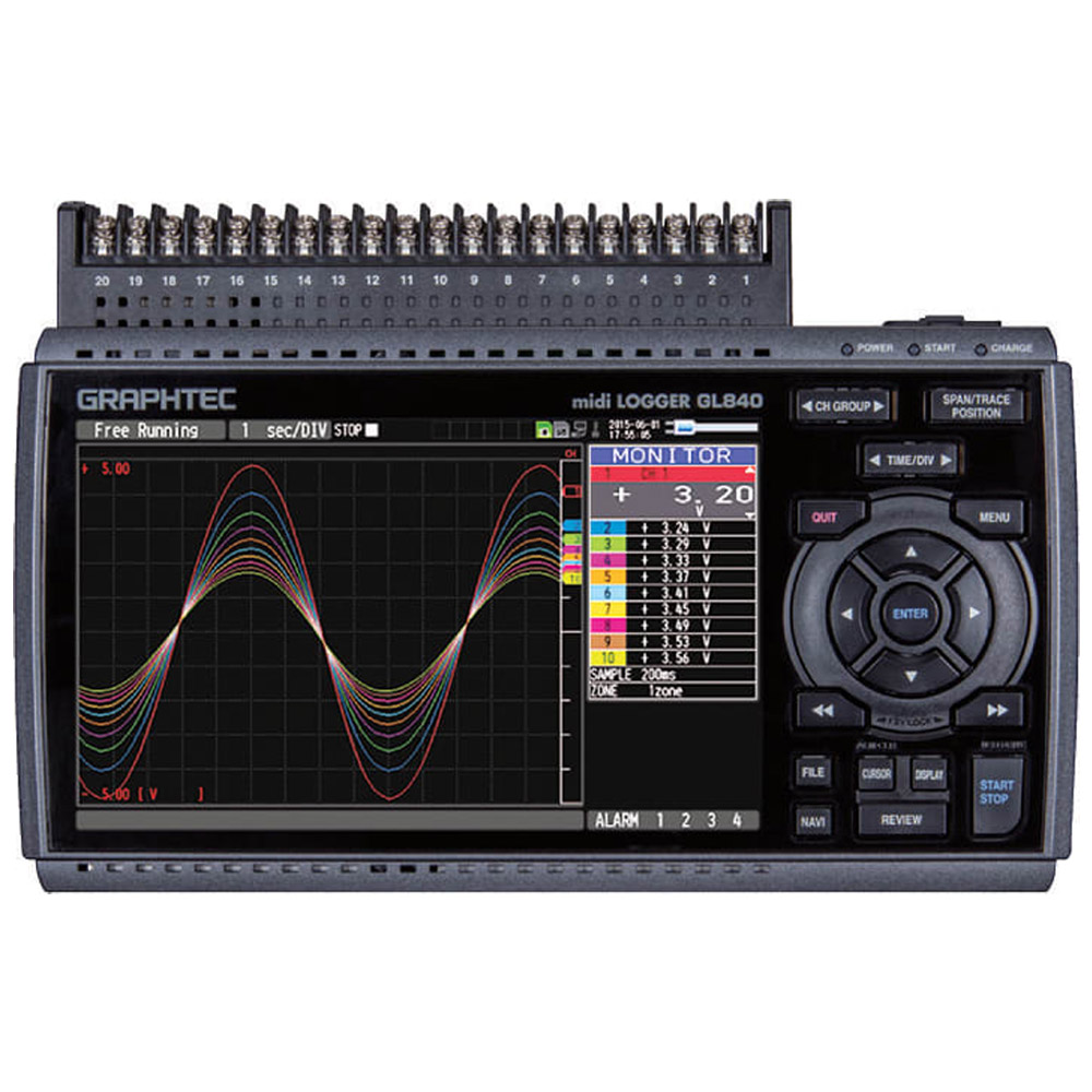
Graphtec GL840M Expandable 20 Channel Datalogger

- Wireless LAN capability | remote monitoring & datalogging
- Flexible input system for wide array of applications | RTD, T/C
- Expandable to 16 total digital channels with optional upgrade
- Ability to access additional (GL100) sensors & adapters
- Extended memory capacity using SD memory card
- Max sampling interval up to 10ms
- Smartphone access
Standalone System
The Graphtec GL840M is a high quality 20 channel datalogger that is expandable up to 200 total channels. Each channel is isolated. This unit is suitable for many applications including temperature measurement with multiple channels. The built in 7 inch color display provides an intuitive data viewing experience. Although this system is designed as a standalone unit, it can be connected to a PC if needed.
Communicate with up to (5) GL100 units with B-568 Wifi module
Multifunction analog input ports
The GL840M has been designed with an extremely isolated input system ensuring that all signals are left unaffected by outside channel noise. With this capability, this system can be used for a variety of applications including voltage, humidity, temperature, pulse and logic.
The GL840M comes standard with 20 analog input channels but it is easily expandable up to 200 channels by adding the optional 20 channel extension terminal base (B-566) and other input terminal units (B-564 or B-565).
Sampling Interval
This is used to set the sampling interval for data capture.The table below shows the number of measuring channels and sampling interval values that can be set.If data fluctuate due to noise, set the sampling interval to a value which enables the digital filter function.
| Number of Measuring Channels*1 | Allowed Sampling Interval | Sampling Interval which enables Digital Filter |
| 1CH | 10ms or slower*2 | 50ms or slower |
| 2CH | 20ms or slower*2 | 125ms or slower |
| 3CH to 5CH | 50ms or slower*2 | 50ms or slower |
| 6CH to 10CH | 00ms or slower | 500ms or slower |
| CH to 20CH | 200ms or slower | 1s or slower |
| 21CH to 50CH | 500ms or slower | 2s or slower |
| 51CH to 100CH | 1s or slower | 5s or slower |
| 1CH to 200CH | 2s or slower | 10s or slower |
*1: «Number of Measuring Channels» is the number of channels in which input settings are NOT set to «OFF». (CHs in GS sensor and terminal/addapter and wireless sensor are not included.)
*2: When the temperature setting is performed in 10, 20, or 50 ms sampling interval, the data capture cannot be performed.
Configuration for additional channels
| Number of Channels | 20 Channels | 40 Channels | 100 Channels | 200 Channels |
| GL840 unit (GL840-M or GL840-WV) | 1 set | 1 set | 1 set | 1 set |
| Connection cable(B-567-05 or -20) | N/A | 1 pc | 1 pc | 1 pc |
| Terminal base (B-566) | N/A | 2 sets | 5 sets | 10 sets |
| Input terminal (B-564 or B-565 ) | N/A | 1 set | 4 sets | 9 sets |
 Ring capture function
The most recent data is saved when the memory is configured in ring memory mode.(Number of capturing data is 1000 to 2000000 points)
 Relay capture function
Data is continuously saved to multiple files up to 2GB without losing any data until capturing is stopped when the memory is configured in the relay mode.
 Hot-swapping the SD memory card
SD card can be replaced during data capturing when the sampling interval is 100ms or slower.
Additional Features
- Alarm output function
- Based on set conditions for each channels, alarm signal can be placed using the four channel alrm out put ports.*
- *Input/Output cable(B-513 option) is required to connect the alrm output ports to external buzzer/light mechanism.
- USB drive mode
- USB drive mode function enables data to be transferred to the PC from GL840 by drag&drop feature.
- Navigation function
- Simple to use navigation screen allows setting operatin for measurement and wireless LAN adapter.
- Large easy-to-read 7-inch wide color LCD
- Carries a clear 7-inch wide TFT color LCD screen (WVGA:800×480 dots) for the GL840. Monitoring data are displayed in waveform or digital form option. Parameter settings can be displayed on the screen.
- 3 Types of power sources
- Choose from AC power supply, DC supply* or the rechargeable battery pack.*
- *DC power drive cable(B-514) and battery pack(B-569) are optional accessories.
- WEB&FTP server function
- GL840 can be controlled externally via a network on the WEB browser, which also supports monitoring and transfer of signals and captured data.
Manufacturer Specs
| GL840 Main unit specifications | |||
| Model number | GL840-M | GL840-WV | |
| Number of analog input channels | 20 channels in standard configuration, Expandable up to 200 channels | ||
| Number of analog input terminals | Up to 10 terminals (20 channels / terminal), standard config: 1 | ||
| Type of analog input terminal | Multi-input type, Withstand-voltage type | ||
| Port for digital sensor | 1 port for the sensor/input terminal/adapter of the GL100 | ||
| External input/ output *1 |
Input *2 | Trigger or Sampling (1 channel), Logic/Pulse (4 channels) | |
| Output *3 | Alarm (4 channels) | ||
| Sampling interval | 10 ms to 1 hour (10ms to 50ms: voltage only) *4, External signal | ||
| Time scale of waveform display | 1 sec. to 24 hour /division | ||
| Trigger, Alarm function |
Trigger action | Start or stop capturing data by the trigger | |
| Repeat action | Off, On (auto rearmed) | ||
| Trigger source | Start: Off, Measured signal, Alarm, External, Clock, Week or Time Stop: Off, Measured signal, Alarm, External, Clock, Week or Time |
||
| Condition Setting | Combination: OR or AND Analog signal: Rising (High), Falling (Low), Window-in, Window-out Logic signal: Pattern (combination of each input signal in high or low) Pulse (number of count): Rising (High), Falling (Low), Window-in, Window-out |
||
| Alarm output | Outputs a signal when alarm condition occurs in the input signal *5 | ||
| Pulse input function |
Rotation count (RPM) mode |
Counts the number of pulses per sampling interval and converts to rpm (rotations per minute), Number of pulses for one rotation can be set to 50, 500, 5000, 50k, 500k, 5M, 50M, 500M rpm/F.S. (rpm./Full Scale) |
|
| Accumulating count mode |
Accumulates the number of pulses from the start of measurement 50, 500, 5000, 50k, 500k, 5M, 50M, 500M C/F.S. (Counts/Full Scale) |
||
| Instant count mode |
Counts the number of pulses per sampling interval 50, 500, 5000, 50k, 500k, 5M, 50M, 500M C/F.S. (Counts/Full Scale) |
||
| Calculation function |
Between channels | Addition, Subtraction, Multiplication, and Division for analog input | |
| Statistical | Select two calculations from Average, Peak, Maximum, Minimum, RMS | ||
| Search function | Search for analog signal levels, values of logic or pulse or alarm point in captured data |
||
| Interface to PC | Ethernet (10 BASE-T/100 BASE-TX), USB (Hi-speed), WLAN (using B-568 option) | ||
| Storage device |
Media | 4 GB Internal Memory SD memory card (Support SDHC, up to 32 GB). Memory card not included |
|
| Saved contents | Captured data, Setting conditions, Screen copy | ||
| Capturing mode | Mode: Normal, Ring, Relay Ring: Saves most recent data (Number of capturing data: 1000 to 2000000 points) *7 Relay: Saves data to multiple files without losing data until dada capturing is stopped |
||
| Replay data | Replays captured data that was saved in the GL840 (in GBD or CSV format) | ||
| Scaling (Engineering unit) function | Measured value can be converted to specified engineering unit • Analog voltage: Converts using four reference points (gain, offset) • Temperature: Converts using two reference points (offset) • Pulse count: Converts using two reference points (gain) |
||
| Action during data capture | • Displaying past data (using dual display mode (Current + Past data)) • Hot-swapping the SD memory card • Saving data in between cursors |
||
| Display | Size | 7-inch TFT color LCD (WVGA: 800 x 480 dots) | |
| Language | English, French, German, Chinese, Korean, Russian, Spanish, Japanese | ||
| Information *8 | Waveform in Y-T with digital values, Waveform only, Digital value, Digital values and statistics values |
||
| Operating environment | 0 to 45 ºC, 5 to 85 % RH (non condensed) (When operating with battery pack 0 to 40 ºC, charging battery 15 to 35 ºC) |
||
| Power source | AC adapter | 100 to 240 V AC, 50/60 Hz (1 pc of adapter is attached as standard accessory) | |
| DC power | 8.5 to 24 V DC (DC drive cable (option B-514) is required) | ||
| Battery pack | Mountable two battery packs (battery pack (option B-517): 7.2V DC, 2900mAh) | ||
| Power consumption *9 | Max. 38 VA | ||
| External dimensions (W x D x H in mm, Excluding projections |
Approx. 240 x 158 x 52.5 | Approx. 240 x 166 x 52.5 | |
| Weight *10 | Approx. 1010 g | Approx. 1035 g | |
- *1 Input/Output cable for GL (option B-513) is required to connect the signal.
- *2 Input signal;
-
- Voltage range: Up to 24V (common ground)
- Signal type: Voltage, Open collector, Contact (relay)
- Threshold: Approx. + 2.5 V (Hysteresis: Approx. 0.5V (2.5V to 3V))
- *3 Output signal: Open collector (pull-up to 5V by 10kΩ resistor)
-
- Voltage: Max. 30V,
- Current: Max. 0.5A,
- Collector dissipation: Max. 0.2W
- *4 Minimum interval varies by number of channels used.
- *5 Output port can be specified in each input channel.
- *7 Size of the capture data will be limited to 1/3 of available memory.
- *8 Display mode is switched every time the dedicated key is pressed. In magnified digital value mode, the displayed channel number can be specified. In the waveform display mode, the changing of the time scale will be effective from the point of the next displayed data.
- *9 Rating under maximum power consumption using the AC adapter, with LCD display on, and battery pack(s) being charged.
- *10 Excludes AC adapter and battery pack.
| Software specifications for PC | |||
| Item | Description | ||
| Supported OS | Windows 8.1, 8, 7, Vista (32/64-bit edition) | ||
| Supported device | GL840 (USB, Ethernet, WLAN), GL100 (USB, WLAN) | ||
| Functions | Control the GL series, Real-time data capture, Replay data, and Data format conversion | ||
| Supported units & channels | Up to 1000 channels total, Up to 4 groups (number of units is limited by model) | ||
| Settings control | Input condition, Capturing condition, Trigger/Alarm condition, Report, etc. | ||
| Capturing data | Saved to PC | Saves captured data in real time (in GBD binary or CSV format) | |
| Saved to GL unit | Saves to the SD memory card (in GBD binary or CSV format) | ||
| Displayed information | Y-T waveform, Digital values, Report, X-Y graph (specified period of data, data reply only), Two displays for the current and past data, and Statistical calculation |
||
| File operation | Converting data format to CSV from GBD binary, merge multiple data files in the time axis or as an additional channel |
||
| Warning function | Send e-mail to the specified address when the alarms occur | ||
| Statistical calculation | Maximum, Minimum, and Avarage during data capturing | ||
| Report function | Creates the daily or monthly report automatically | ||
| Software specifications for Smart device | ||
| Model name | GL-Connect | |
| Supported OS | Android 4.1 to 4.4, iOS 7/8 | |
| Supported device | GL840 (WLAN), GL100 (WLAN) | |
| Functions | Control the GL series, Display measured data in waveform or digital value | |
| Supported units | Up to 10 units | |
| Settings control | Start/Stop, Sampling interval | |
| Capturing data | Saves captured data in the GL main body (data cannot be saved in the smart device) | |
| Displayed information | Data captured in real time by digital value, Replay the data stored in the GL body by the waveform | |
| Wireless LAN unit (option) specifications | ||
| Model number | B-568 | |
| Supported device | GL840 | |
| Communication method | Wireless communication (using radio waves in the 2.4GHz band) | |
| Supported WLAN system | IEEE802.11b/g/n WPS: Push button or PIN method Security protocols: WEP64, WEP128, WPA-PSK/WPA2-PSK, AKIP/AES Communication distance: Approx. 40m (depending on the conditions of radio communication) |
|
| Installed location | Attached to the SD CARD slot number 2 on the GL840 * When the wireless LAN unit is installed, the SD memory card cannot be used in slot number 2 |
|
| Function | Access Point mode: Communicate with the GL100-WL as a remote sensor (captured data in the GL100-WL is transferred to GL840) Station mode: Communicate with PC or Smart device (control GL840 and transfer the data from GL840) |
|
| Connected number of GL100-WL | GL840: Up to 5 units of the GL100-WL | |
| GL840 Analog input specifications | |||||
| Model number | GL840-M, Input terminal B-564 | GL840-WV, Input terminal B-565 | |||
| Input method | All channels isolated balanced input *11, Scans channels for sampling | ||||
| Type of input terminal | Screw terminal (M3 screw) | ||||
| Measurement range |
Voltage | 20, 50, 100, 200, 500 mV, 1, 2, 5, 10, 20, 50, 100 V, and 1-5V F.S. (Full Scale) | |||
| Thermocouple | Type: K, J, E, T, R, S, B, N, W (WRe5-26) Range: 100, 500, 2000 ºC *12 |
||||
| RTD (Resistance Temperature Detector) |
Type: Pt100, JPt100 (JIS), Pt1000 (IEC751) Range: 100, 500, 2000 ºC *12 |
||||
| Humidity | 0 to 100 % RH – using the humidity sensor (option B-530) | ||||
| Filter | Off, 2, 5, 10, 20, 40 (moving average in selected number) | ||||
| Measurement accuracy *13 | |||||
| Voltage | ± 0.1% of F.S. (Full Scale) | ± (0.05% of F.S. + 10μV) | |||
| Temperature (Thermocouple) *14 | |||||
| Type | Measurement range (TS: Temp Sense) |
Measurement accuracy | Measurement accuracy | ||
| R | 0 ≤ TS ≤ 100 ºC | ± 5.2 ºC | ± 4.5 ºC | ||
| 100 < TS ≤ 300 ºC | ± 3.0 ºC | ± 3.0 ºC | |||
| 300 < TS ≤ 1600 ºC | ± (0.05% of rdg. + 2.0 ºC) | ± 2.2 ºC | |||
| S | 0 ≤ TS ≤ 100 ºC | ± 5.2 ºC | ± 4.5 ºC | ||
| 100 < TS ≤ 300 ºC | ± 3.0 ºC | ± 3.0 ºC | |||
| 300 < TS ≤ 1760 ºC | ± (0.05% of rdg. + 2.0 ºC) | ± 2.2 ºC | |||
| B | 400 ≤ TS ≤ 600 ºC | ± 3.5 ºC | ± 3.5 ºC | ||
| 600 < TS ≤ 1820 ºC | ± (0.05% of rdg. + 2.0 ºC) | ± 2.5 ºC | |||
| K | -200 ≤ TS ≤ -100 ºC | ± (0.05% of rdg. + 2.0 ºC) | ± 1.5 ºC | ||
| -100 < TS ≤ 1370 ºC | ± (0.05% of rdg. + 1.0 ºC) | ± 0.8 ºC | |||
| E | -200 ≤ TS ≤ -100 ºC | ± (0.05% of rdg. + 2.0 ºC) | ± 1.0 ºC | ||
| -100 < TS ≤ 800 ºC | ± (0.05% of rdg. + 1.0 ºC) | ± 0.8 ºC | |||
| T | -200 ≤ TS ≤ -100 ºC | ± (0.1% of rdg. + 1.5 ºC) | ± 1.5 ºC | ||
| -100 < TS ≤ 400 ºC | ± (0.1% of rdg. + 0.5 ºC) | ± 0.6 ºC | |||
| J | -200 ≤ TS ≤ -100 ºC | ± 2.7 ºC | ± 1.0 ºC | ||
| -100 < TS ≤ 100 ºC | ± 1.7 ºC | ± 0.8 ºC | |||
| 100 < TS ≤ 1100 ºC | ± (0.05% of rdg. + 1.0 ºC) | ± 0.6 ºC | |||
| N | -200 ≤ TS < 0 ºC | ± (0.1% of rdg. + 2.0 ºC) | ± 2.2 ºC | ||
| 0 ≤ TS ≤ 1300 ºC | ± (0.1% of rdg. + 1.0 ºC) | ± 1.0 ºC | |||
| W | 0 ≤ TS ≤ 2000 ºC | ± (0.1% of rdg. + 1.5 ºC) | ± 1.8 ºC | ||
| R.J.C. | ± 0.5 ºC | ± 0.3 ºC | |||
| Temperature (RTD) *15 | |||||
| Type | Measurement range (TS: Temp Sense) |
Accuracy | Accuracy | ||
| Pt100 | -200 ≤ TS ≤ 100 ºC | ± 1.0 ºC | ± 0.6 ºC | ||
| 100 < TS ≤ 500 ºC | ± 0.8 ºC | ||||
| 500 < TS ≤ 850 ºC | ± 1.0 ºC | ||||
| JPt100 | -200 ≤ TS ≤ 100 ºC | ± 0.8 ºC | ± 0.6 ºC | ||
| 100 < TS ≤ 500 ºC | ± 0.8 ºC | ||||
| Pt1000 | -200 ≤ TS ≤ 100 ºC | ± 0.8 ºC | ± 0.6 ºC | ||
| 100 < TS ≤ 500 ºC | ± 0.8 ºC | ||||
| A/D converter | Sigma-Delta type, 16 bits (effective resolution: 1/40000 of the measuring full range) | ||||
| Maximum input voltage |
Between (+) / (-) terminal |
20 mV to 2 V range: 60 Vp-p, 5 V to 100 V range: 110 Vp-p |
|||
| Channels ((-) / (-)) | 60 Vp-p | 600 Vp-p | |||
| Channel / GND | 60 Vp-p | 300 Vp-p | |||
| Max. voltage (withstand) |
Between channels | 350 Vp-p (1 minute) | 600 Vp-p | ||
| Channel / GND | 350 Vp-p (1 minute) | 2300 Vrms AC (1 minute) | |||
- *11The terminal «b» for using the RTD is connected each other across all channels.
- *12 If the specifications of the temperature sensor is lesser or greater than the selected measurement range, GL840 can measure up to the specifications of the sensor.
- *13 Subject to the following conditions:
-
- Room temperature is 23 oC ± 5 oC.
- When 30 minutes or more have elapsed after power has turned on.
- Filter is set to 10.
- Sampling rate is set to 1 sec, using 20-channel in GL840-M and 10-channel in GL840-WV.
- GND terminal is connected to ground.
- *14 Wire size of thermocouple used is 0.32mm diameter in the T type and 0.65mm diameter in other types.
- *15 Supports 3-wire type sensor.
| B-569 Optional Battery Information | |
| Item | Description |
| Capacity | 7.2V / 2900mAh |
| Battery type | Lithium secondary battery |
| Running time | Up to two packs can be mounted
Battery pack x 1 (brightness MAX): approx. 3 hours Battery pack x 1: approx. 5 hours |
| Charging method | Mount in the main unit |
| Time required to charging | Battery pack x 1: approx. 5 hours Battery pack x 2: approx. 10 hours |
| Switch over in the event of a power failure | Because the battery is used together with the AC adapter, the power supply will be switched automatically to the battery in the event of a power failure. *The AC adapter is the primary power source. |
| Operation environment | Running on battery: 0 to 40°C Battery being charged: 15 to 35°C |
| Other functions | *When the battery is running low, file is closed automatically *Remaining amount indicator |
Tech Specs
Dataloggers / Data Acquisition/Data Recorders Template |
|
|---|---|
| Type (Recorders) | DAQ System, Data Logger |
| Style (Recorders) | Bench / Portable, Panel Mount, PC Based |
| # Channels Expanded plus Logic (Recorders) | 200 EA |
| # Channels Base Unit (Recorders) | 20 EA |
| Display (Recorders) | Built-in, Included w/ Base Unit |
| # Logic / Digital Channels (Recorders) | 4 |
| Sampling Interval (Controllers/Recorders) | 10 ms |
| Sampling Frequency (Recorders) | 100 kS/S (0.1 MS/S) |
| Input Types (Controllers/Recorders) | Current / 4-20 mA, Digital / Logic / On-Off, Frequency / Pulse, T/C – RTD, Voltage |
| Output Types (Controllers/Recorders) | Relay |
| Bits | 16 |
| Power Source | Battery, DC Line |
| Screen Size | 7.0 IN |
| Built-in Sensors (Recorders) | Humidity (RH), Pulse / Frequency, Temperature |
| Special Functions (Recorders) | External Trigger, Flow / Speed Totalization, Logic / Ladder / Math, PC Software Available, Software / Visible Alarms |
| Data storage | Yes |
| # Data Points | 2000000 |
| Isolated Inputs (Recorders) | Yes |
| Accuracy | Voltage: ± 0.1% of F.S. (Full Scale)
Temperature (Thermocouple)
|
Test Equipment General Attributes |
|
| Unique Features | – Standalone/Portable Datalogger
– Wireless WLAN option – Ability to connect up to 200 channels – Additional wireless connection with up to 5 GL100-WL compact dataloggers using the main GL840 as a hot spot access point. |
| Warranty | 1 YEARS |
| Safety Approval | CE, UL |
| Interfaces I/O | LAN / Ethernet, Web Host / Web Server, Wifi, Analog Input , USB |
| Storage | Internal Memory, SD Card |
| Product Weight | 2.2 LBS |
| Product Height | 6.22 IN |
| Product Length | 2.0 IN |
| Product Width | 9.5 IN |
| Data Logging | Yes |
| HTS/Schedule B Number | 9027.20.8090 |
| ECCN Number | EAR99 |
| Calibration Included | Factory Calibration, NIST Calibration |
| Battery Type | Li-ion |
| Power Supply Voltage | 120V/220V Universal, Battery Powered |
| Country of Origin | Japan |


Valoraciones
No hay valoraciones aún.